Friday, June 24, 2016

4.6 Blog: Unmanned System Data Protocol and Format


RQ-4 Global Hawk

Gabriel P. Riccio

4.5 Research Assignment Unmanned System Data Protocol and Format

UNSY 605 Unmanned Systems Sensing, Perception, and Processing

Embry-Riddle Aeronautical University-Worldwide


      The RQ-4 Global Hawk is a highly sophisticated unmanned aerial system (UAS) capable of performing high altitude, long endurance (HALE) aerial surveillance and reconnaissance over large geographical areas for the purpose of providing data to battlefield commanders ("RQ-40 Block 40 Global Hawk," 2012).  Outfitted with air to surface radar, the Global Hawk can monitor both fixed and moving targets in all weather conditions (“RQ-40 Block 40 Global Hawk," 2012).  The platform grew out of a 1990s DARPA (Defense Advanced Research Projects Agency) program ("Northrop Grumman RQ-4 Global Hawk - Copybook," n.d.).  The first Global Hawk produced by Northrop Grumman was the RQ-4A Block 10; the most current version is Block 40 ("Northrop Grumman RQ-4 Global Hawk - Copybook," n.d.).  A breakdown of the nomenclature RQ-4 is as follows: the “R” means reconnaissance, the “Q” means unmanned, and the digit “4” represents the fourth type ("Northrop Grumman RQ-4 Global Hawk - Copybook," n.d.).
       The original RQ-4A was equipped with electro-optical and infrared sensors along with synthetic aperture radar (SAR) ("Northrop Grumman RQ-4 Global Hawk - Copybook," n.d.). Later models of the Global Hawk came with imagery intelligence sensors, airborne signal intelligence payload sensors, the multi-platform radar technology insertion program system, and active electronically scanned array radar  ("Northrop Grumman RQ-4 Global Hawk - Copybook," n.d.).  It is important to highlight that the Global Hawk is a complete system.  In addition to the aircraft and payloads/sensors, it establishes data links for data download; it is controlled by the ground stations, and requires a lot of logistical support (Kinzig, 2010).  The on-board communication system enables command and control of the platform, its payload, and the ability to transfer data (Kinzig, 2010).  The data can be disseminated by ultra-high frequency line of sight (UHF LOS), common data link line of site (CDL LOS), Ku band satellite communications, UHF satellite communications, and other satellite communications (Kinzig, 2010).
Figure 1. The many methods of disseminating Global Hawk data. Adapted from “Global Hawk systems engineering case study” by B. Kinzig (2010). Retrieved from www.dtic.mil/dtic/tr/fulltext/u2/a538761.pdf
As stated previously, the biggest evolution in the platform has been the upgrades to the
sensor packages.  The imagery intelligence payload which consists of the electro-optical and
infrared sensor (EO/IR), and synthetic aperture radar (SAR) collect high resolution imagery for the purpose of intelligence gathering (RQ-4B Global Hawk block 30 operational test and evaluation report, 2011).  Radio frequency signals are collected by the signal intelligence payload whereupon they are processed to support intelligence operations; additionally they are capable of automatic signal detection, the location of the signal, signal direction, and signal identification (RQ-4B Global Hawk block 30 operational test and evaluation report, 2011). Refer to Figure 1 and Figure 2 to for sensor summary data.  The data formats are NTIF (National Imagery Format) standard 2.1 meaning the data format complies with prescribed military standards which increase capability and flexibility as compared to previous formats ("National Imagery Transmission Format Standard (NITFS)”, n.d.).  NITF 2.1 does have backward compatibility with earlier formats; it includes JPEG (Joint Photographic Experts Group) compression, newer decompression algorithms, and CGM (Computer Graphics Metafile) for graphics (“National Imagery Transmission Format Standard (NITFS)”, (n.d.).
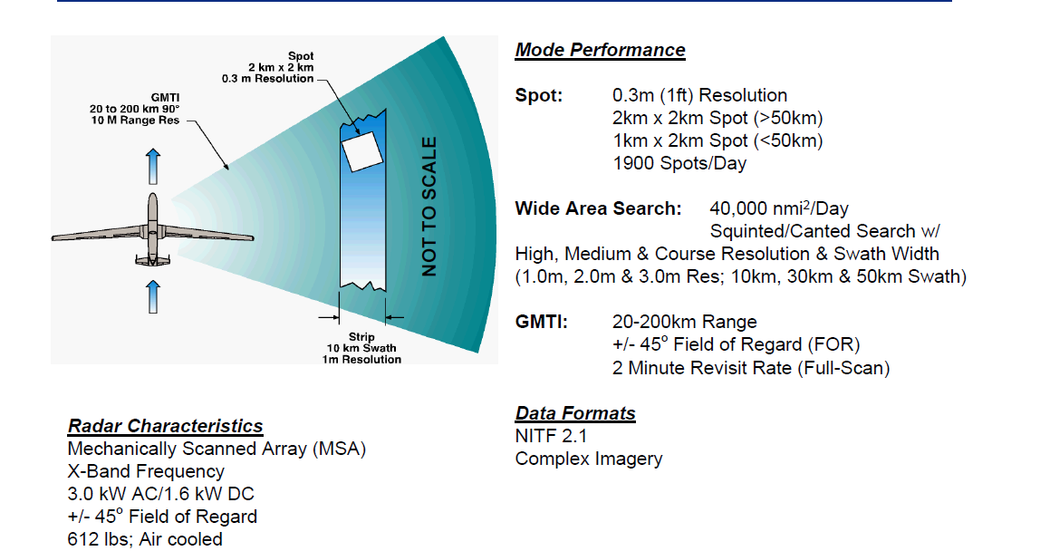
Figure 2. Global Hawk SAR sensor summary data. Adapted from “Global Hawk program overview”, (2011). Retrieved from https://www.faa.gov/about/office_org/headquarters_offices/avs/offices/aam/cami/library/online_libraries/aerospace_medicine/sd/media/GH_Program_Overview_Briefing.pdf
Figure 3. Global Hawk EO/IR sensory summary data. Adapted from “Global Hawk program overview”, (2011). Retrieved from https://www.faa.gov/about/office_org/headquarters_offices/avs/offices/aam/cami/library/online_libraries/aerospace_medicine/sd/media/GH_Program_Overview_Briefing.pdf
       The Global Hawk will most likely continue to upgrade its sensor suite as technology improves, and or the mission changes. As of Block 30, there are no means for the Global Hawk to conduct autonomous operations and record data if data links are lost. During this research, it was discovered that it was recommended in the “RQ-4B Global Hawk block 30 operational test and evaluation report”, (2011) that data recording be implemented for “off-tether” missions.  All research on Block 40 indicates that data recording functionality has not been implemented as of yet.  Therefore, it is recommended that this functionality be added to meet operational needs in the event of a communications failure from the UAS to the control station. Additionally, during this research, power required for the sensor payload suites were not listed; however the platform has an on-board electric generator which supplies 25 kilo-volt-amperes to the platforms AC (alternating current) electrical system (Kinzig, 2010).

References
Kinzig, B. (2010). Global Hawk systems engineering case study.  Air Force Center for Systems Engineering, Air Force Institute of Technology, Wright Patterson, OH. Retrieved from www.dtic.mil/dtic/tr/fulltext/u2/a538761.pdf
National Imagery Transmission Format Standard (NITFS). (n.d.). Retrieved from http://www.globalsecurity.org/intell/systems/nitfs.htm
Northrop Grumman RQ-4 Global Hawk - Copybook. (n.d.). Retrieved from http://www.copybook.com/military/fact-files/northrop-grumman-rq-4-global-hawk
RQ-4B Global Hawk block 30 operational test and evaluation report. (2011). Retrieved from http://pogoarchives.org/m/ns/pentagon-ot-and-e-eval-rq-4b-global-hawk-20110526.pdf


Thursday, June 16, 2016

UAS Sensor Placement


Unmanned Aerial Systems (UAS) have been growing in popularity for several years for both professionals and hobbyists.   There are many UAS purchase choices available that can be used in a variety of applications.  This research assignment will focus on two such UAS; the first is the Yuneec Typhoon Q500 4K, capable of full motion video and still picture photography, and the second UAS is the Vortex 250 Pro, predominately used in first person view (FPV) racing; along with their associated sensor placement.

            Sensors on UAS need to be strategically placed to maximize their effectiveness and protect them from unforeseen hazards.  It is important for companies to develop sensor placement strategies for their products.  A good sensor placement strategy can improve the overall efficiency of a sensor such as in global positioning navigation (Vitus & Tomlin, 2010).  It has also been shown that an efficient strategic sensor placement plan can increase software algorithm performance (Vitus & Tomlin, 2010).

            The Typhoon Q500 4K manufactured by Yuneec Electric Aviation is a market competitive quadcopter similar in specification to the popular DJI Phantom 3 (Estes, 2015).  When selecting a UAS for the purpose of high quality image collection, it is important to select a platform with high quality sensors (“UAV sensors, n.d.).  An understanding of the light spectrum will help potential buyers pick optic sensors that meet their desired needs (“UAV sensors”, n.d.).  Visible light sensors, near infrared sensors, and infrared sensors are each capable of capturing a specific light band that falls within the electromagnetic spectrum (“UAV sensors”, n.d.).  Therefore, it is important to purchase the right sensor for the intended application and ensure its placement on the UAS will produce effective results.  The Q500 4K utilizes a visible light sensor that can be used across a variety of applications such in agriculture, surveying, forestry, and surveillance (“UAV sensors”, n.d.).  The stabilized camera is capable of 1080p adjustable high definition imagery with slow motion capability, and can take 12-megapixel still pictures (Estes, 2015).  The 1080p, 4K camera is mounted to the CG03 gimbal that yields a 130-degree field of view due to its placement below the main body (Amato, 2015).  The camera is modular, meaning it can be detached from the UAS for future sensor and payload upgrades (Amato, 2015).
Figure 1.  Picture of the Typhoon Q500 4k quadcopter. Adapted from “Yuneec announces new world class drone” by S. Patel (2015). Retrieved from http://www.guysgab.com/yuneec-announces-new-world-class-drone/

            Another vital sensor installed on the Typhoon Q500 is the global positioning system (GPS) receiver.  This sensor enables the pilot to easily fly and control the UAS.  The Q500 can be flown if GPS coverage is lost, however, it is more difficult to control.  GPS also creates a geo-fence (virtual barrier), that will keep the Q500 within a 300 foot perimeter of the operator if selected; additionally, if for some reason GPS connectivity is lost, the Q500 will automatically fly back to the pilot’s location ("Typhoon Q500 4K instructional manual," n.d.).  GPS sensor placement is important to ensure reliable signal reception.  It is important to remember, that GPS signal coverage may be lost if the quadcopter is flown indoors.  If the GPS receiver is connected to at least seven satellites, the “Follow Me” mode can be selected which will enable the Q500 to follow the pilot at selected altitude.

            When discussing first person view (FPV) UAS racing, the Vortex 250Pro is a competitive and reasonable purchase.  FPV UAS racing, also known as quadcopter racing is somewhat of a new phenomenon growing in popularity (Anthony, 2016).  During FPV racing, the pilot wears a pair of goggles that receives a video feed from the FPV UAS, so the racer can be controlled (Anthony, 2016).
Figure 2.  Image of the Vortex 250 Pro. Adapted from “Immersion Vortex 250 Pro FPV Quadcopter” (2015). Retrieved from http://www.dronetrest.com/t/immersionrc-vortex-250-pro-fpv-quadcopter/1418

The Vortex 250 Pro camera mount can support a flight cam or a high definition camera ("ImmersionRC Vortex 250 Pro FPV quadcopter - Product - DroneTrest," 2015).  It is important that the camera be mounted in a position so it can provide the pilot with needed perspective to successfully navigate the FPV UAS racecourse, which could include obstacles.  The camera is protected by its placement in the UAS from impacts and is supported by vibration dampened carbon fiber plate ("ImmersionRC Vortex 250 Pro FPV quadcopter - Product - DroneTrest," 2015).

            Most FPV UAS racers, when purchased, do not include the goggles.  The goggles are not required to fly the drone, but if they will enhance the experience, and if the UAS is used for racing, based on my research, the goggles are a requirement to be competitive.  The goggles are what the pilot wears, to allow them to optically fly the platform.  It is recommended that the optics are glass and have a digital head tracking technology, along with a field of view between 25% - 45% ("The ultimate FPV system guide 2016 - Best drone goggles", 2016).  The camera on the UAS racer transmits a feed to the receiver, which in turn transmits the feed to a display ("The ultimate FPV system guide - Everything explained - DroneUplift," n.d.).
Figure 3. The basic setup of FPV UAS system. Adapted from “The ultimate FPV system guide - Everything explained - DroneUplift," (n.d.). Retrieved from http://www.droneuplift.com/the-ultimate-fpv-system-guide-everything-explained/

            The Vortex 250 Pro also has an integrated full-graphic on screen display, an on board black box that collects and records flight data for tuning purposes, 40 channel NexWaveRF video, and seven 32bit dedicated ARM (advanced RISC machine) processors ("ImmersionRC Vortex 250 Pro FPV quadcopter - Product - DroneTrest," 2015).

            Whether the UAS is used for aerial photography or for FPV racing, sensor placement is important.  If UAS sensors are not strategically placed they will not achieve peak performance, nor will they be protected from an unwanted crash. 


References

Amato, A. (2015, April 2). Yuneec Q500 Typhoon review - DRONELIFE. Retrieved from http://dronelife.com/2015/04/02/dronelife-reviews-the-yuneec-q500-typhoon/

Anthony, S. (2016, January 28). First-person drone racing is much harder than I expected | Ars Technica. Retrieved from http://arstechnica.com/gadgets/2016/01/first-person-drone-racing-is-much-harder-than-i-expected/

Estes, A. (2015, September 28). Yuneec Typhoon Q500 4K review: This is my new favorite drone. Retrieved from http://gizmodo.com/yuneec-typhoon-q500-4k-review-this-is-my-new-favorite-1731109743

ImmersionRC Vortex 250 Pro FPV quadcopter - Product - DroneTrest. (2015, November). Retrieved from http://www.dronetrest.com/t/immersionrc-vortex-250-pro-fpv-quadcopter/1418

Patel, S. (2015, July 14). Yuneec announces new world class drone - Guys Gab. Retrieved from http://www.guysgab.com/yuneec-announces-new-world-class-drone/

The ultimate FPV system guide - Everything explained - DroneUplift. (n.d.). Retrieved from http://www.droneuplift.com/the-ultimate-fpv-system-guide-everything-explained/

The ultimate FPV system guide 2016 - Best drone goggles. (2016). Retrieved from http://www.dronethusiast.com/the-ultimate-fpv-system-guide/

Typhoon Q500 4K instructional manual. (n.d.). Retrieved from https://www.wellbots.com/content/Yuneec/q500_4k_user_manual.pdf

UAV sensors. (n.d.). Retrieved from http://www.questuav.com/news/uav-sensors

Vitus, M., & Tomlin, C. (2010). Sensor placement for improved robotic navigation. Retrieved from http://www.roboticsproceedings.org/rss06/p28.pdf

Thursday, June 9, 2016

2.5 Blog Activity: Unmanned Systems Maritime Search and Rescue


On May 31, 2009, Air France flight 447 took off from Rio de Janeiro, Brazil enroute to Paris, France.  However, the Airbus A330 with 228 souls on board was lost over the Atlantic Ocean (Wise, 2011).  The cause of the crash was unknown, and French aviation authorities were challenged to locate the accident site, in an effort to recover the aircraft’s flight data recorders also known as the “black boxes” (Wise, 2011).  Oceanographic experts were solicited for help to narrow the search pattern to a reasonable area.

Three Remus 6000 unmanned maritime vehicles (UMVs) were tasked to conduct the underwater search (Wise, 2011).  On April 3, 2011, the Airbus A330 wreckage was found by one of the Remus 6000 UMVs at a depth of 13,000 feet (Koberth-Baker, 2011). This discovery led to the recovery of the flight data recorder and cockpit voice recorder, which helped to answer questions for investigators and give closure to the families of the deceased ("How statisticians found Air France Flight 447 two years after it crashed into Atlantic," 2014).

The Remus 6000 is designed to operate autonomously in deep water, down to almost 20,000 feet carrying a suite of sophisticated sensors ("Remus 6000 Deep Ocean, large area search/survey”, n.d.).  The UMV uses acoustic navigation to survey the search area, and sensors to collect and record data; the vehicle also has a high-resolution imaging system mounted on its bottom to analyze areas of interest ("Remus 6000 Deep Ocean, large area search/survey”, n.d.). Some general specifications for the REMUS 6000 are as follows:

·         Diameter – 28 inches

·         Length – 12.6 feet

·         Weight – 1900 pounds

·         Max operating depth – 19,685 feet or 3.7 miles

·         Endurance – Up to 22 hours ("Remus 6000 Deep Ocean, large area search/survey”, n.d.).

Proprioceptive and exteroceptive sensors contribute to the success of the Remus 6000. The proprioceptive sensors allow the device to maintain heading and speed; all the data is obtained from within the internal environment of the UMV (Clarks, 2011).  The exteroceptive sensors get their input from data collected from the UMVs external environment (Clark, 2011).

Proprioceptive sensors include:

1.      Inertial Navigation Unit (INU): This system consists of accelerometers and gyros which measure the UMVs surge, sway, and heave.  This data is used to compute speed and distance.

2.      Conductivity, Temperature, and Depth Sensor (CTD): This sensor determines ocean water salinity, UMV depth, and water temperature.

3.      GPS/Iridium/Wi-Fi Antenna: This one antenna serves three functions. When operating on the surface GPS location can be determined, enables the UMV to call the control station with its location, and connects to the control stations shipboard computer via a Wi-Fi or iridium satellite connection ("Remus 6000 Deep Ocean, large area search/survey”, n.d.).

Exteroceptive sensors include:

1.      Acoustic Doppler Current Profiler (ADCP): Pulses are bounced off the seafloor to calculate ground speed and depth.

2.      Pencil-Beam Sonar Collision Avoidance System: Sound pulses are transmitted out in front of the UMV, these pulses bounce off of any potential obstacles so the UMV can alter its path to avoid an unwanted collision.

3.      Dual-frequency Side-Scan Sonar: Speakers and microphones are used to ping the seafloor with sound waves to map a 2-dimensional image.

4.      Custom Digital Camera with Strobe Light: When the UMV is 10 meters above the seafloor, it is synced with a strobe light to take digital photographs, which are tagged with position and time.

5.      Multibeam Profiling Sonar: Sonar beams ping the seafloor to produce a 3-dimensional map.

6.   Sub-Bottom Profiling Sonar: Sound beams are used to find objects buried below the seafloor sediment ("Remus 6000 Deep Ocean, large area search/survey”, n.d.).

            One modification that could be made to the REMUS 6000 to make it more successful in maritime search and rescue operations is to outfit the UMV with the ability to tow a smaller sized UMV that is tethered from the control station ship to the wreckage site.  As of now the Remus 6000 can only search and locate.  As in the crash of Air France flight 447, after the wreckage was discovered larger and more capable UMVs had to be brought in to retrieve the wreckage (Wise, 2011).  This smaller sized UMV could be brought to the site by the REMUS 6000 whereupon it can stay indefinitely, providing data and video to the control station.  Additionally, the Remus 6000 could transmit the data collected to the smaller sized UMV whereupon the data would be transmitted to the control station via the tether to the ship, so it could immediately be analyzed.

            UMVs coupled and integrated with Unmanned Aerial Systems (UAS) would increase the effectiveness of maritime search and rescue operations.  This idea of integrating different unmanned platforms to work cooperatively in maritime search and rescue operations is not new.  Currently ICARUS, also known as Integrated Components for Assisted Rescue and Unmanned Search operations is exploring and creating a means for autonomous Unmanned Service Vehicles and UAS to work as part of an integrated team in maritime related disasters ("ICARUS Unmanned Maritime Search and Rescue System Demonstrated in Portugal | Unmanned Systems Technology," 2015).  ICARUS is a shared network among unmanned systems devoted to detecting, locating, and saving lives during times of disasters for accidents ("ICARUS Unmanned Maritime Search and Rescue System Demonstrated in Portugal | Unmanned Systems Technology," 2015).  Integrating the REMUS into the ICARUS plan will provide one more proven tool into maritime search and rescue.

            Unmanned systems such as the REMUS 6000 have one distinct advantage over their manned counterparts; the lack of the man.  Manned operators require space in which to operate the UMV, along with food, water, and oxygen to name a few.  The UMV has to be larger to accommodate the operator and all of the necessary supplies, which in turn can increase overall vehicle weight and operating costs.  Underwater search operations can take many months or in the case of Air France flight 447, two years.  This is an exceptional amount of time to be spent under the sea looking for evidence of a wreckage.  This is dangerous work, and anytime risk to human life can be mitigated it should.  Accidents can happen, even to those who are doing the searching and the rescuing.  At some point in maritime search and rescue operations humans may be required to get involved because the autonomous unmanned platforms cannot complete the task, but it should be out of necessity.

            The effectiveness of the suite of sensors for both unmanned and manned systems in theory is the same; a sensor is a sensor.  If an unmanned system and manned system are both the same size, then most likely more sensors could be incorporated into the system occupying the space that the operator formerly occupied.  If the same data is being collected by both systems with the same sensors, and the mission can be performed autonomously, then it should.


References

Clark, C. (2011). COS 495 - Lecture 7 Autonomous robot navigation [PowerPoint Slides]. Retrieved from https://www.cs.princeton.edu/courses/archive/fall11/cos495/COS495-Lecture7-SensorCharacteristics.pdf 

How statisticians found Air France Flight 447 two years after it crashed into Atlantic. (2014, May 27). Retrieved from https://www.technologyreview.com/s/527506/how-statisticians-found-air-france-flight-447-two-years-after-it-crashed-into-atlantic/

ICARUS Unmanned Maritime Search and Rescue System Demonstrated in Portugal | Unmanned Systems Technology. (2015, July 20). Retrieved from http://www.unmannedsystemstechnology.com/2015/07/icarus-unmanned-maritime-search-and-rescue-system-demonstrated-in-portugal/ 

Koberth-Baker, M. (2011, May 6). Air France 447: How scientists found a needle in a haystack / Boing Boing. Retrieved from http://boingboing.net/2011/05/06/air-france-447-how-s.html

Remus 6000 Deep Ocean, large area search/survey. (n.d.). Retrieved from https://www.whoi.edu/main/remus6000

Wise, J. (2011, December 6). Air France 447 flight-data recorder transcript - what really happened aboard Air France 447. Retrieved from http://www.popularmechanics.com/flight/a3115/what-really-happened-aboard-air-france-447-6611877/


Friday, June 3, 2016

1.5 Blog Activity Setup and First Entry


This assignment is a requirement to summarize a news or journal article that highlights a sensor employed on an unmanned system.

S. Greene (2013), wrote an article for The Colorado Independent titled “Mesa County, Colo. A National Leader in Domestic Drone Use”. The article discusses Colorado’s use of police Unmanned Aerial Vehicles (UAVs). The Mesa County Sheriff’s Department flies the UAVs mounted with state of the art cameras, covering an area of 3,300 square miles (Greene, 2013). The county flies UAVs equipped with camera sensors and thermal imagining sensors to capture data used in police operations such as search and rescue operations, police chases, and crime scene reconstruction (Greene, 2013). As compared to manned helicopter operations, the UAVs outfitted with their sensors, save a significant amount of money.
One of the most notable concerns with police flying UAVs equipped with camera, and video sensors is the issue of privacy. The Mesa County Sheriff’s Department has had many calls from concerned citizens about the use of the UAVs for surveillance operations (Greene, 2013). The department has strived to ensure the public that they will not use the UAVs for any purpose that conflicts with the law or their standard operating procedures (Greene, 2013).
If it was not for the advanced sensor technology, there would be no practical use for UAVs in a police application. The high resolution cameras and thermal imaging sensors make it possible for the UAVs to capture detailed imagery in both day and night conditions.  The high resolution camera will allow smaller objects to be viewed at greater distances with more detail ("Thermal imagers," n.d). Thermal imaging sensors detect infrared energy emitted, transmitted, or reflected off of objects and convert that energy into a viewable display ("Thermal imagers," n.d). In addition to using thermal imaging in law enforcement applications, thermal imaging is used by many other professionals such as firefighters to see through smoke, and powerline maintenance technicians to detect hot spots ("Top uses and applications of thermal imaging cameras - Quick tips #345 - Grainger Industrial Supply," n.d.). Mesa County also hopes to use their two UAVs in the future to help determine the volume of a local landfill, and track wildfires (Greene, 2013).
References:
Greene, S. (2013, June 6). Colorado’s Mesa County a National leader in domestic drone use | The Colorado Independent. Retrieved from http://www.coloradoindependent.com/127870/colorados-mesa-county-a-national-leader-in-domestic-drone-use

Thermal imagers. (n.d.). Retrieved from http://www.omega.com/prodinfo/thermal_imagers.html

Top uses and applications of thermal imaging cameras - Quick tips #345 - Grainger Industrial Supply. (n.d.). Retrieved from https://www.grainger.com/content/qt-thermal-imaging-applications-uses-features-345